|
AFBR-S50 API Reference Manual v1.6.6
AFBR-S50 Time-of-Flight Sensor SDK for Embedded Software
|
|
AFBR-S50 API Reference Manual v1.6.6
AFBR-S50 Time-of-Flight Sensor SDK for Embedded Software
|
The AFBR-S50 Reference Board by MikroElektronika is a fully featured hardware reference design that can be used to kick-start the integration of the AFBR-S50 sensors into the users application. The AFBR-S50 Reference Board can be directly integrated into the application or used as a hardware reference design to evaluate a custom design.
Official Link: https://www.mikroe.com/bdc-afbr-s50-tof-sensor-board
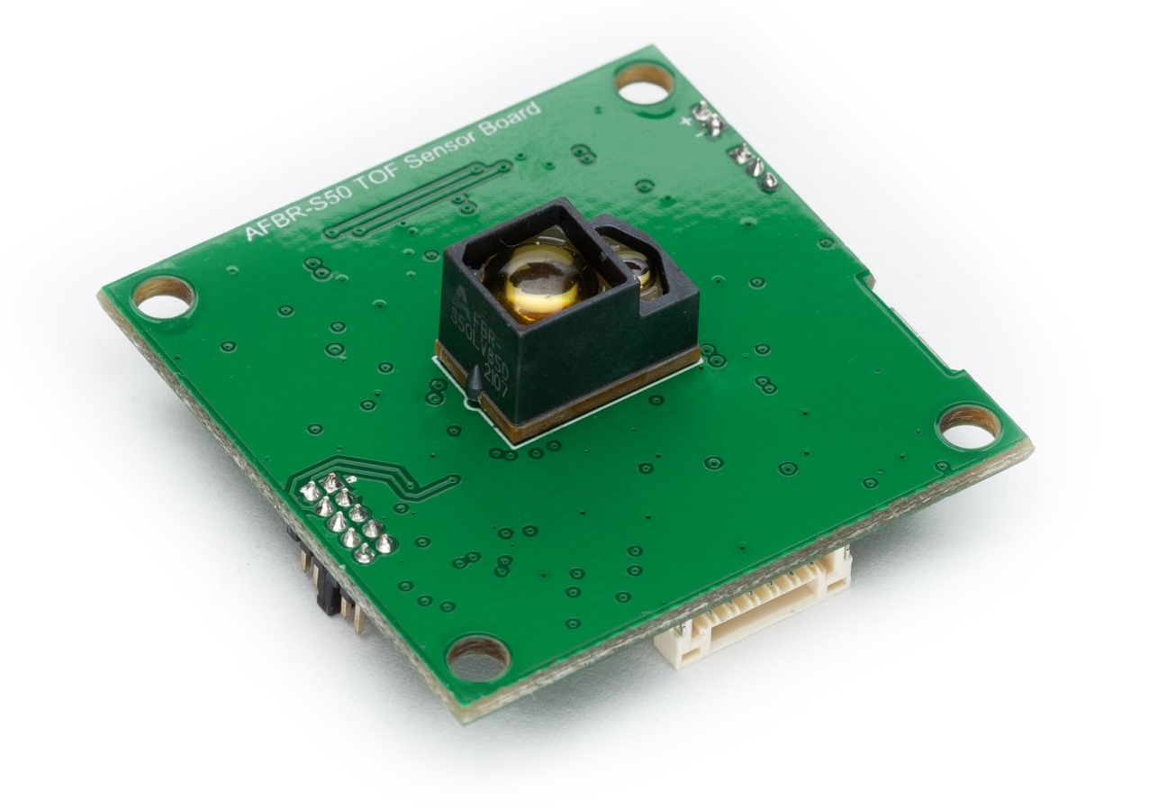
Highlight features of the AFBR-S50 Reference Board are
VEXT) (2-pin header with 1.27 mm pitch)The AFBR-S50 Reference Board is based on the Renesas R7FA4M2AD3CFL (100 MHz ARM® Cortex®-M33 ) chip.
Get started on using the board by flashing the desired firmware to the board via the Bootloader feature. Refer to the corresponding application documentation on how to use it here: Demo Applications
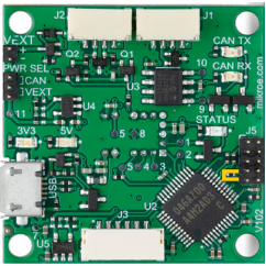
The following ways can be used to power the board:
VEXT pin header (J6). The jumper PWR SEL must be set to VEXT.PWR SEL (J4) must be set to CAN. See CAN-Bus Connector section for pin configuration.The AFBR-s50 Reference Board features a Micro-USB port (CN1) that is connected to the Renesas RA4M2 USB pins. Thus, it can be used to make the board an USB device as well as utilizing the built-in bootloader to flash new firmware into the MCU.
The built-in bootloader is accessible via the micro-USB connector (CN1). In order to boot in bootloader mode, a jumper must be set to connect pins 7 and 9 of the J5 header (i.e. the SWD interface).
File >> New Project....Microcontroller: RAProject Name: create your project nameProject Folder: your project folder pathCommunication Tool: COM Port >> Tool Details...: your COM Port number 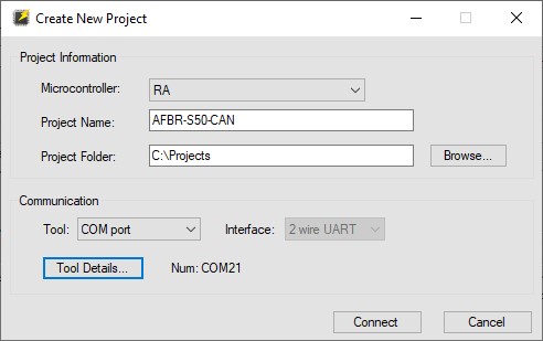
Connect.*.srec, *.hex, etc.) and Click Start.operation completed is displaying at the console. 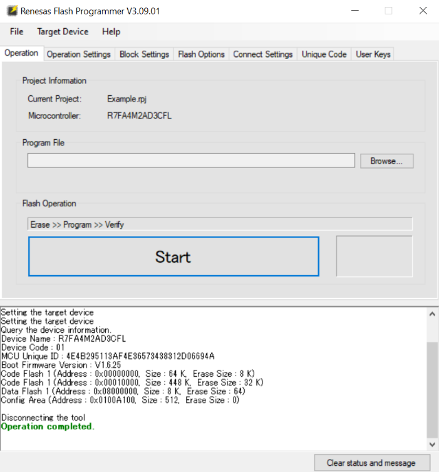
The board features two CAN-Bus connectors (J1 and J2). These are 4 pin connectors where CANH is on pin 2 and CANL is on pin 3. The connector can also be used to power the AFBR-S50 Reference Board by applying 5V to pin 1. Pin 4 functions as GND pin. Note that the PWR SEL jumper (J4) must be set to CAN.
| J1 / J2 | USB-CAN |
|---|---|
| 1: 5V_CAN | N/C |
| 2: CANH | CANH |
| 3: CANL | CANL |
| 4: GND | GND |
To connect the AFBR-S50 Reference Board via CAN interface to the PC, an appropriate CAN-to-USB adapter is required (e.g. the USB to CAN Analyzer Adapter by SeeedStudio).
The board features a UART connection via the J3 connector. It is a 6 pin connector where TX is on pin 3 and RX is on pin 2. The connector can also be used to power the AFBR-S50 Reference Board by applying 5V to pin 1. Pin 6 functions as GND pin.
Also see the Powering the Board section for alternative ways on powering the board.
To connect the AFBR-S50 Reference Board via UART interface to the PC, an appropriate Serial-to-USB adapter is required (e.g. the FT232H Breakout Board by Adafruit).
| AFBR-S50 Reference Board | Serial-to-USB FTDI Adapter |
|---|---|
| J3-1: 5V | 5V (optional) |
| J3-2: RXD | TX (e.g. D0 @ FT232H) |
| J3-3: TXD | RX (e.g. D1 @ FT232H) |
| J3-4: n/c | - |
| J3-5: n/c | - |
| J3-6: GND | GND |