|
AFBR-S50 API Reference Manual v1.6.5
AFBR-S50 Time-of-Flight Sensor SDK for Embedded Software
|
|
AFBR-S50 API Reference Manual v1.6.5
AFBR-S50 Time-of-Flight Sensor SDK for Embedded Software
|
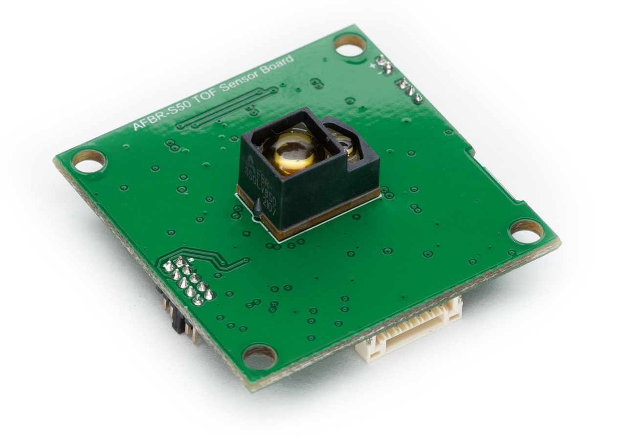
The AFBR-S50 Reference Board by MikroElektronika runs with a simple CAN demo application, the CAN App.

It provides a CAN connection to another Node that is starting and stopping the TOF measurements.
See Bootloader for details.
In order to run the provided CAN App project using the e² Studio IDE by Renesas, follow the steps in the e² Studio IDE section to import, build and run/debug the AFBR_S50_CANApp_RA4M2 project. Skip steps that connect to UART and connect to via CAN-Bus software instead.
See the CAN-Bus Connector section on more details on how to connect to the AFBR-S50 Reference Board via CAN-Bus.
Once the connection is established and the board is powered, it waits for the measurement start command. The start command can be provided by CAN or UART. After receiving the start command, it starts streaming (1D) measurement data via CAN interface until a stop measurements command is received. Here is an overview of currently available CAN commands:
| ID | Type | Data | Name | Description |
|---|---|---|---|---|
| 0x08 | Remote | - | Start Measurements | Start the measurement cycle on the board. |
| 0x09 | Remote | - | Stop Measurements | Stops the measurement cycle on the board. |
| 0x28 | Data | 8-bytes | 1D Measurement Data | A set of 1D measurement data including range, amplitude, status and signal quality values. |
Data Frame (0x28) Description:
| Value | Units | Bytes | Data Type | Description |
|---|---|---|---|---|
| Range | mm | 0-2 | 24-bit unsigned int | Range value in millimeters. |
| Amplitude | LSB | 3-4 | 16-bit unsigned int | Amplitude value in LSB. |
| Signal Quality | % | 5 | 8-bit unsigned int | Signal Quality in % (1: bad, 100: good; 0: n/a) |
| Status | - | 6-7 | 16-bit signed int | Measurement Status (0: OK, <0: Error, >0 Warning/Status, see status_t for details) |
Here is an overview of currently available UART commands:
| Character | Name | Description |
|---|---|---|
| s | Start Measurements | Starts the measurement cycle on the board. |
| p | Stop Measurements | Stops the measurement cycle on the board. |
A Controller Are Network (CAN) is a robust bus standard designed to communicate with each others applications without a host. The protocol is message-based. The data in a frame is transmitted serially, but if more than one node is transmitting at the same time, the highest priority device can continue while the others back off. Every Node is receiving the same frames.
CAN is a multi-master serial bus standard for nodes. Two or more nodes are required. The bus uses differential wired-AND signals, a physically conventional two wire bus. CAN High and CAN Low signal is terminated with 120 Ohm characteristic impedance.
The CAN protocol defines the data link layer and part of the physical layer in the OSI model.
To sum up:
CAN specifies two logical levels: recessive and dominant. At the ISO-11898 recessive and dominant states are defines as differential voltages. The recessive state is defined as logical 1, and for the dominants it is defined as logical 0.
Basis frame according ISO 11898-1:
| Start | Identifier | RTR | IDE | r0 | DLC | DATA | CRC | ACK | EOF+IFS |
|---|---|---|---|---|---|---|---|---|---|
| 1Bit | 11Bit | 1Bit | 1Bit | 1Bit | 4Bit | 0..8Bytes | 16Bit | 2Bit | 10Bit |
Extended-Frame according ISO 11898-1:
| Start | Identifier | SRR | IDE | Identifier | RTR | r1 | r0 | DLC | Data | CRC | ACK | EOF+IFS |
|---|---|---|---|---|---|---|---|---|---|---|---|---|
| 1Bit | 11Bit | 1Bit | 1Bit | 18Bit | 1Bit | 1Bytes | 1Bit | 4Bit | 0..8Bytes | 16Bit | 2Bit | 10Bit |
With sending a remote frame a node is requesting the data from the source.
An Error frame consists of 2 fields:
//TODO
CAN uses a Carrier Sense Multiple Access/ Collision Avoidance (CSMA/CA) method. It checks whether the bus is occupied or not (carrier sense). With sending simultaneously (multiple access) the arbitration process will be effective.
There are some arbitration levels to follow
If there's always no difference between the frames, an bit error will occur.
TODO