|
AFBR-S50 API Reference Manual v1.6.6
AFBR-S50 Time-of-Flight Sensor SDK for Embedded Software
|
|
AFBR-S50 API Reference Manual v1.6.6
AFBR-S50 Time-of-Flight Sensor SDK for Embedded Software
|
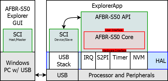
The Evaluation Kit runs with a demo application, the Explorer App. It establishes an USB or UART connection to the AFBR-S50 Explorer GUI that is running on a Windows PC. The Explorer App provides a serial interface that allows the GUI to transfer configuration and calibration parameters and receive measurement data.
The Explorer App hosts the AFBR-S50 Core Library and connects it to a a Serial Communication Interface (SCI) to allow accessing the sensor from the PC. The SCI implements an API that is equivalent to the AFBR-S50 API, but accessible via a serial peripheral interface such as USB or UART. The SCI is an communication protocol that can be ported to almost every serial communication interface. The Explorer App functions as the communication device, while an external host, e.g. the AFBR-S50 Explorer GUI running on a Windows machine, is implemented as a controller.
The following chapter gives an overview about the architecture and implementation of the SCI module in the Explorer App. After gaining a basic understanding of the implementation, it should be an easy task to adopt the Explorer App along with the interface to the user requirements and create the host interface that can connect to the provided SCI.
Note: from SDK version v1.4.4 onwards, the Explorer App is able to connect to multiple devices at the same time. This can be either achieved by using multiple evaluation kits and establishing an unique USB/UART connection to each board or by using a multi-device adapter board and run multiple instances of the AFBR-S50 API on a single MCU.
The source files are located in Sources/ExplorerApp of the AFBR-S50 GitHub repository and the projects are located in Project/<IDE>/AFBR_S50_ExplorerApp_<MCU>, depending on your target. The following target/IDE combinations are provided:
| MCU | IDE | Path | Comment |
|---|---|---|---|
| NXP MKL46z | MCUXpressoIDE | Projects/MCUXpressoIDE/AFBR_S50_ExplorerApp_KL46z | Runs on FRDM-KL46Z evaluation board by NXP |
| NXP MKL17z | MCUXpressoIDE | Projects/MCUXpressoIDE/AFBR_S50_ExplorerApp_KL17z | |
| STM32 F401RE | STM32CubeIDE | Projects/STM32CubeIDE/AFBR_S50_ExplorerApp_F401RE | Runs on NUCLEO-F401RE evaluation board by STM |
| Renesas RA4M2 | e² Studio | Projects/e2Studio/AFBR_S50_ExplorerApp_RA4M2 | Runs on AFBR-S50 Reference Board by MikroElektronika |
See also Build And Run Projects for an overview of featured boards/MCUs/IDEs and how to import and build the project in the corresponding IDE. Just follow the steps and skip the steps that connect to a serial terminal. and connect via USB or UART with a SCI controller (e.g. using the AFBR-S50 Explorer GUI or the Python example) instead.
The basic idea is to define simple commands (= 7-bit values) to access the AFBR-S50 API. These commands are either transactions with or without data phase. Usually, the commands with data phase are simple getter and setter commands, e.g. "get distance" or "set frame rate".
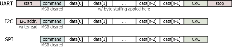
Each data package starts by the identifier byte (= command byte), followed by a predefined number of data bytes which may be zero. Finally, the package finishes with a CRC byte to verify the data integrity. These byte sequences are called data frames.
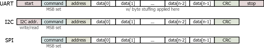
A new feature is the addressing mechanism which has been introduces with SDK v1.4.4. The addressing mechanism allows to connect to multiple devices at the same time. In order to distinguish between commands with and without addressing, the 8th bit of the command byte is used. If the 8th bit is set, the command will contain an addressing byte immediately after the command byte. Otherwise, the command has not addressing byte and it is addressed to the default device.
The data frames are transmitted in different manner dependent on the underlying hardware interface. However, at a higher level, the command or message layer does not depend on the hardware interface. The communication happens between various systems, whereby one of them needs to be the master. All other participants are slaves which are controlled by the master. Depending on the underlying hardware, there can be a single (e.g. UART) or multiple (e.g. SPI or I2C) slaves. In case of the latter, the slaves are addressed by the master via the corresponding hardware architecture.
Each command to a slave is acknowledged after successful execution. If any error occurs, a not-acknowledge is invoked by the slave. Only a single command can be sent to the slave at once, i.e. the slave has to (not-)acknowledge the command before the master can send another one. A timeout can be implemented in the master to check if the slave responds within a given time and is still alive or if it is stuck in some invalid state.
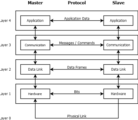
The architecture of the SCI (see Fig. 5.2) consists of several layer. Each is communicating on a specific level with its corresponding counterpart.
The lowermost layer is the hardware layer which is the hardware abstraction layer for the underlying hardware, e.g. UART or I2C. The hardware layer transfers data bits over a physical link.
The second layer is the data link layer. It takes care about a reliable transmission of data frames, i.e. a bunch of associated bytes. Therefore it is responsible for putting together data by framing it with a start and a stop byte. It also applies the byte stuffing and finally adds an CRC value to allow the detection of invalid frames.
The third layer is the protocol or message layer. Its responsibility is to transfer messages or commands via the data link layer. In order to achieve a reliable connection, the handshaking is also implemented into this layer via acknowledgment messages.
The last and uppermost layer is the Application or API layer. It provides high level functionality to transfer application specific data.
To sum up:
The UART interface support only point-to-point communications. It has an independent line for sending as well as receiving data and the slave can transmit data at any time without special actions from the master are required. Therefore, this mode does not require an interrupt line to inform the master about new data ready or error conditions. The data is just transmitted immediately which means that the master must always listen to its Rx line.
The data framing is realized with byte stuffing. There are three special bytes, the start, stop and escape bytes, that are used to determine the boundaries of a data frame. In order to make the start and stop bytes unique and keep the full data range per byte, the corresponding data bytes are inverted and escaped with the escape byte.
In order to provide a handshaking mechanism, the slave acknowledges the successful reception of an data frame (and the successful invocation of the corresponding command) with a short ACK (= acknowledged) or NAK (= not_acknowledged) message within a define time.
Furthermore, due to the independent TX line, the special feature of log and error messages are supported by the UART protocol.
The SPI interface support multiple slave mode via the chip select (CS) lines. Data transfers can only be initiated by the master and thus an extra IRQ line is used to give the slave a chance to call the masters attention to it. This is however optional and the alternative method would be polling the status by the master.
The data framing is realized via the CS. After the command byte, the data is transferred either by on the MISO or MOSI for a read or write command respectively.
The handshaking is implemented via the IRQ line. If an error occurs, the IRQ is pulled to low. The master can now read the corresponding status in order to get the root cause of the IRQ. Also the new measurement ready event is determined via the IRQ. In addition, the acknowledgment of the successful reception and execution of a command could be implemented via the interrupt; the master would responsible for reading the acknowledge status.
The I2C interface supports multiple slave mode via the device address bytes. Data transfers can only be initiated by the master and thus an extra IRQ line is used to give the slave a chance to call the masters attention to it. This is however optional and the alternative method would be polling the status by the master.
The data framing is realized via the usual I2C protocol. Every frame is started with the I2C start condition followed by the devices write address and then master writes the command. In case of a write command, the data can follow immediately. In case of an read command, the devices read address is placed after an repeated start condition. The slave will put its data to the SDA line afterwards.
Besides the already build-in acknowledgment mechanism form the I2C protocol, the reception of an invalid data frame is advertised via the IRQ line. If an error occurs, the IRQ is pulled to low. The master can now read the corresponding status in order to get the root cause of the IRQ. Also the new measurement ready event is determined via the IRQ. In addition, the In addition, the acknowledgment of the successful reception and execution of a command could be implemented via the interrupt; the master would responsible for reading the acknowledge status.
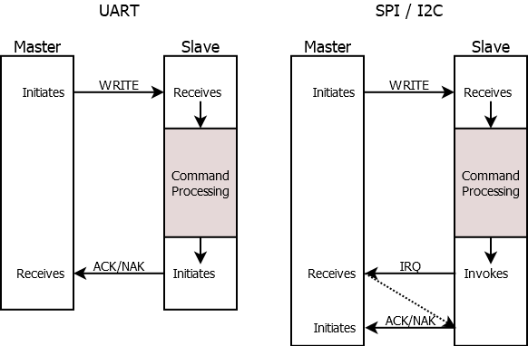
In case of UART, the master simply send data via its Tx line. After processing, the slave responds with an acknowledge or not-acknowledge signal on the masters Rx line.
In case of SPI or I2C, the slave can not send data without the master initiating the transfer. Thus, an additional IRQ is used to give the slave the chance to call the masters attention. In case of no IRQ available, the master must poll the slave on a regular basis. So after processing, the slave signals when he is ready to send the acknowledge or not-acknowledge signal and afterwards the master must initiate the transfer from slave to master.
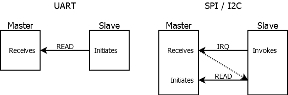
In case of UART, the slave simply sends data via its Tx line. After receiving on the master, the sent data is dismissed. If an error occurs, the master is responsible to react accordingly, e.g. re-initiating the transfer by re-sending the previous command.
In case of SPI or I2C, the slave can not send data without the master initiating the transfer. Thus, an additional IRQ is used to give the slave the chance to call the masters attention. In case of no IRQ available, the master must poll the slave on a regular basis. The slave signals when he wants to send data via the IRQ and afterwards the master must initiate the transfer from slave to master.
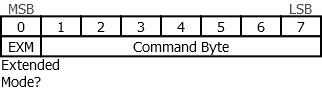
Every command message is identified by the first byte in a data frame. This byte is an unique number that is mapped to a specified parameter/value/command.
The command identifier consists of 7-bit. The MSB is used to determine the difference between an message with (MSB=1) or without (MSB=0) addressing byte.
Reserved Command Bytes
| Byte | Comment |
|---|---|
| 0x02 | ASCII: Start of text |
| 0x03 | ASCII: End of text |
| 0x1B | ASCII: Escape |
| 0x21 | ASCII: ! - reserved for later use |
| 0x23 | ASCII: # - reserved for later use |
| 0x24 | ASCII: $ - reserved for later use |
| 0x3F | ASCII: ? - reserved for later use |
Since version 1.4.4 of the SDK, a new addressing mechanism has been introduced. The new addressing mechanism is based on the command byte format. The MSB of the command byte is used to determine if the message is addressed to a specific device or not. If the MSB is set to 1, the message is addressed to a specific device. In this case, the next byte in the data frame is the address byte. The address byte is the byte that immediately follows the command byte. Some commands do not require an address byte. In this case, the address byte is omitted and the command byte is followed by the data bytes. In this case, the MSB of the command byte is set to 0.
Sending a message without device address is considered equivalent to sending the message with device address 0. If the device address is omitted, the message is sent to the default device, usually the first device in the device list.
Thus, there are two kind of frames:
There are several command types defined:
Thus a single command byte can have up to three different intentions.
Each message or command that is sent over underlying hardware is put into a data frame. A data frame is a sequence of bytes with variable length that contains arbitrary data. Depending on the hardware, the boundaries of the data frames are given in an unique way.
The first byte within a data frame is the command byte that uniquely determines the purpose and thus the format of the data frame. The last byte within the data frame is the security byte that contains a CRC value that guarantees the data integrity of the receive frame. Between the command and CRC bytes, there is an optional data phase of arbitrary length. The format and interpretation of the data is determined by the command byte in the higher layers of the communication stack and does not have any influence for the data framing. Note that the addressing byte is equivalent to the data bytes and does not require any special treatment here.
In case of SPI and I2C, the data framing is incorporated into the hardware protocol itself, while for the UART interface, a software solution is implemented. The SPI data frame is given by the chip select signal. Each data byte that comes while the chip select line stays at low are combined to a single frame until the chip select is released. The I2C protocol implements an embedded start and stop signal that gives the boundaries of a single data frame.
The UART version implements the data framing in software via byte stuffing, since there is no mechanism to detect the start of a new data package build into the hardware interface. The ideas is to reserve some unique byte values to serve as special control signal, e.g. start and stop bytes. Now, all bytes within a start and a stop byte are interpreted as data bytes for a single data frame. In order to not loose the full range of 256 valid values per data byte, an additional escape signal is introduced. Whenever a byte value equal to the value of start, stop or escape byte appears as a data byte within the current frame, an escape byte is added prior to the byte in question in order to signal that the following value is not an control signal but an ordinary data value. In order to increase security further, escaped data bytes are inverted to make the three control values unique.
Here are the control byte definitions:
| Name | Byte | Comment |
|---|---|---|
| Start Flag | 0x02 | ASCII: Start of text |
| Stop Flag | 0x03 | ASCII: End of text |
| Escape Flag | 0x1B | ASCII: Escape |
The algorithm to send a data frame with byte stuffing:
The algorithm to receive data with byte stuffing:
In order to guarantee the data integrity of the received data frame, a CRC value is added to each data frame.
CRC8_SAE_J1850_ZERO definitions:
| Name | Byte |
|---|---|
| CRC Generator Byte | 0x1D |
| CRC Start Value | 0x00 |
Refer to the following link to verify your implementation of the CRC8_SAE_J1850_ZERO algorithm:
Go to: Command Overview
Go to: Command Details
Here is an example that sets some configuration parameters (i.e. data output = 1D data only; measurement frame rate = 5 Hz) and starts timer based measurements. The range is extracted from the received data structure and printed to the console.
The example is very basic though. The sent data frames are manually created (i.e. data encoding, byte stuffing and CRC are hard coded). It ignores the received Acknowledge/NotAcknowledge commands and cannot handle unexpected data from the device.
The file runs with Python (3.6) and requires the Python serial module (pySerial).
Please find the file in [INSTALL_DIR]\Device\Examples\sci_python_example.py (default is C:\Program Files (x86)\Broadcom\AFBR-S50 SDK\Device\Examples\sci_python_example.py).